
Overview
This project is a simple example of DC motor control circuit using L293D driver. The main control board is UNO R3 with ATMega328P microcontroller. It is used to read data from water sensor and pass signals to L293D controller. Motor itself is supplied with 5V from separate power supply board. Both, the motor supply and UNO R3 board have separate power sources, because the UNO R3 board pinouts are rated for 40mA maximum and used DC motor requires approximate 100mA to run.
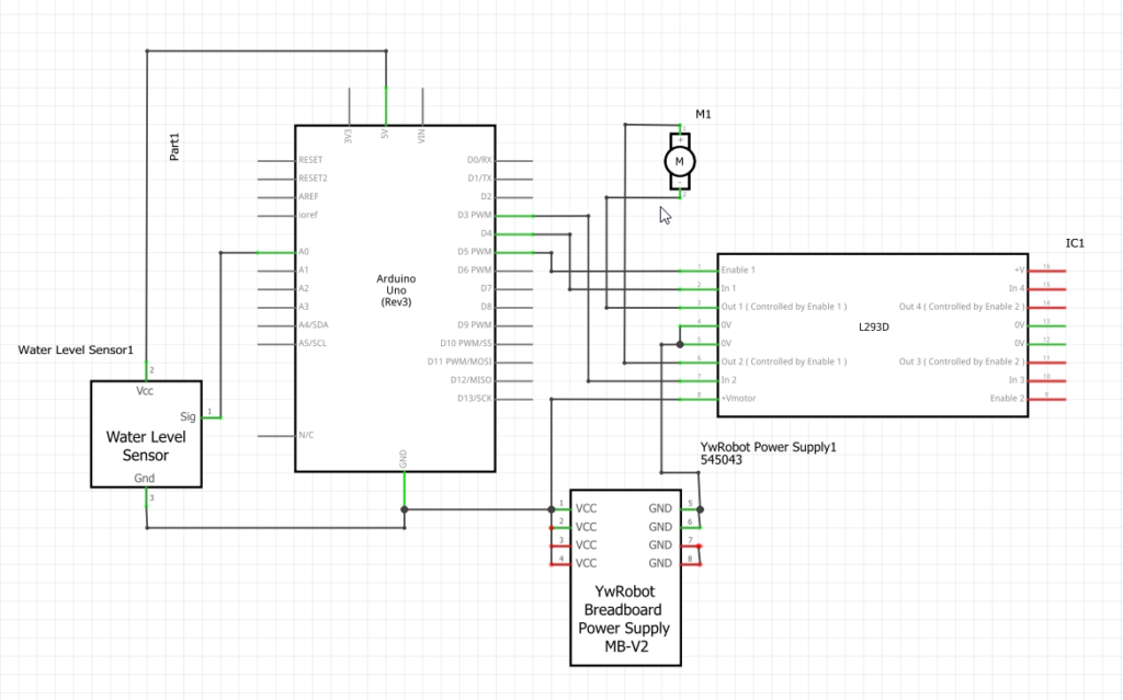
DC Motor Control L293D Schematic
Parts
Elegoo UNO R3
Microcontroller board based on the ATmega328. It is an open-source, prototyping platform and its simplicity makes it ideal for hobbyists to use as well as professionals. The Uno R3 has 14 digital input/output pins (of which 6 can be used as PWM outputs), 6 analog inputs, a 16 MHz crystal oscillator, a USB connection, a power jack, an ICSP header, and a reset button.

Elegoo UNO R3 Microcontroller Board

You can buy this board at these links:
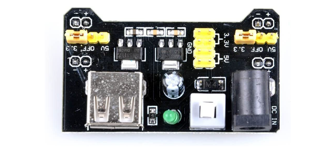
Power Supply Module 3.3V 5V
Additional power supply board for the DC motor. Specification’s state that it will drive motors up to 700mA, which is plenty enough for this application.
- Input voltage: 6.5 – 12V
- Two Independent Channel
- Output voltage: 5V, 3.3V (adjustable via jumpers. 0V, 3.3V, and 5V configuration)
- Output current: Maximum output current 700mA
Power Supply Board Up To 700mA
It is very important to use this module as UNO R3 pinouts are not rated high enough to drive any components over 50mA. If you are trying to run something with less power draw, you still have to consider inducted current protection, by wiring in flyback diode across the motor connections.
L293D Motor Control Driver
The L293D is a popular 16-Pin Motor Driver IC. As the name suggests it is mainly used to drive motors. A single L293D IC is capable of running two DC motors at the same time; also the direction of these two motors can be controlled independently. Only one side of the chip is used with one DC motor.
L293D Schematics
The purpose of this is to control directions of the motor with transistors and also take care of inducted current when the power supply is disconnected – the flyback diode setup takes care of that, as seen on the schematics above.
DC Motor 1-6V
DC Motor 5V
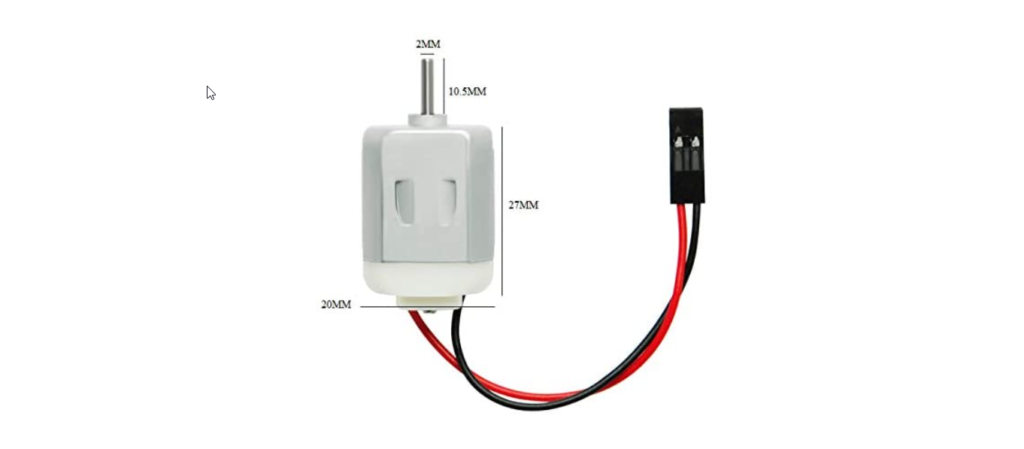
DC motor that will operate on 5V DC power supply. You can find them here:
Water Sensor
Water Level Sensor 20mA

Water level sensor, with current draw of 20mA, which will be suitable for this application.
Find it at this link:
Other Components
Using breadboard for motor controller chip and external power source module installation. This offer solderless designing and prototyping.
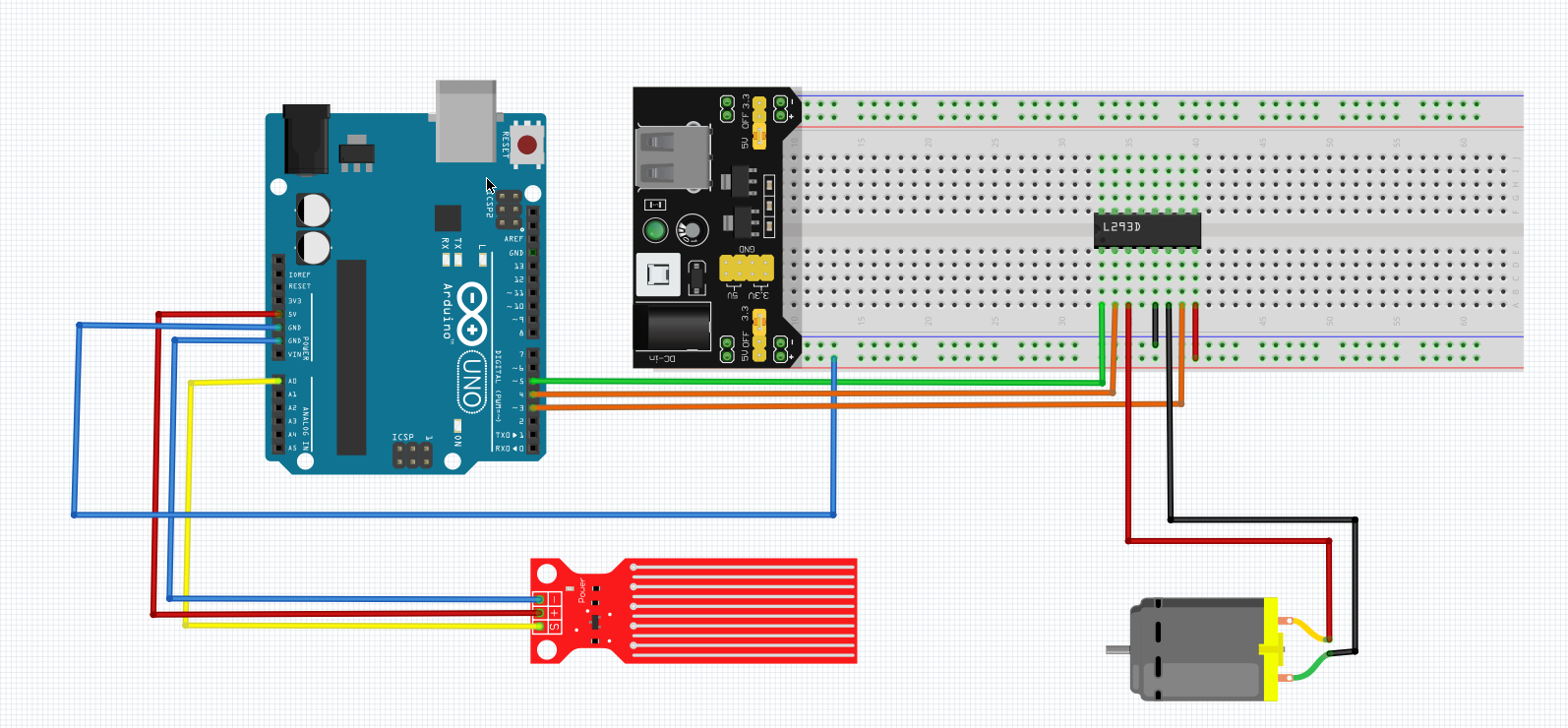
Breadboard Wiring Diagram
It’s important to have common ground between external power source and UNO R3 controller.
DC Motor Control Wiring Diagram
Functionality & Logic
When the sensor is submerged in water, the voltage on pin S will be between 0 – 1V.
UNO R3 analog input reads the voltage and translates it to digital value between 0 – 255.
This value is then passed via pin 6 UNO R3 to pin 1 of the driver.
Pin 3 & 4 are used to set 0V (low) and 5V (high) on pin 2 & 7 of the motor controller.
Pin 3 set to low & pin 4 set to high will result in clockwise direction and vice versa.
Propeller attached to DC motor will dry the sensor’s surface causing readings to drop down and stop the motor.
Program
int speedPin = 5;
int directionPin1 = 4;
int directionPin2 = 3;
int motorSpeed = 255; // 0 - 255 (100-255)
int waterValue = 0;
const int waterSensor = A0;
void setup() {
  // setup
pinMode(speedPin, OUTPUT);
pinMode(directionPin1, OUTPUT);
pinMode(directionPin2, OUTPUT);
pinMode(waterSensor, INPUT);
Serial.begin(9600);
}
void loop() {
  // loop
waterValue = analogRead(waterSensor);
Serial.println(waterValue);
if (waterValue > 10) {
  motorSpeed = 255;
}
else {
  motorSpeed = 0;
}
digitalWrite(directionPin1, LOW);
digitalWrite(directionPin2, HIGH);
analogWrite(speedPin, motorSpeed);
}
Demonstration
Short demonstration of the automated process that can be used in various scenarios, for example:
- water tank low level with solenoid valve top up functionality
- rain detector with step motor
- leaks detector
Measurments
When the sensor reads >10 units, value of 255 is present on pin 5 digital output (microcontroller), which sets the motor speed to maximum. Current draw of DC motor is approximately 102mA. The voltage drop at the water sensor is approx. 0.25V.
DC Motor Current Draw
