
A Full Adder is a logical circuit that performs an addition operation on binary numbers. The full adder produces a sum of three inputs and carry value. Here is a step by step explanation on how I approached this type of circuit in Python.
Logic Form Of Full Adder Circuit
Let’s have a look at the full adder circuit constructed from:
two XOR gates
two AND gates
one OR gate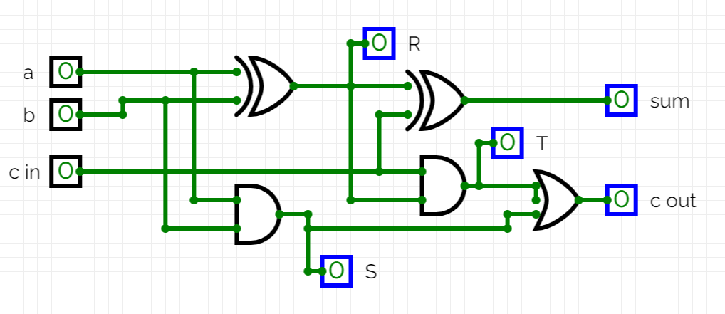
As shown on above diagram, this circuit takes 3 inputs – (a), (b) and carry bit (c).
It outputs two bits – (sum) and carry (c).
Truth Table
We can design a truth table for the above circuit as follow:
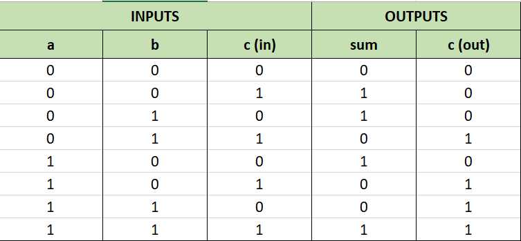
For example, let’s modify the input bits as follow:
a = 1
b = 0
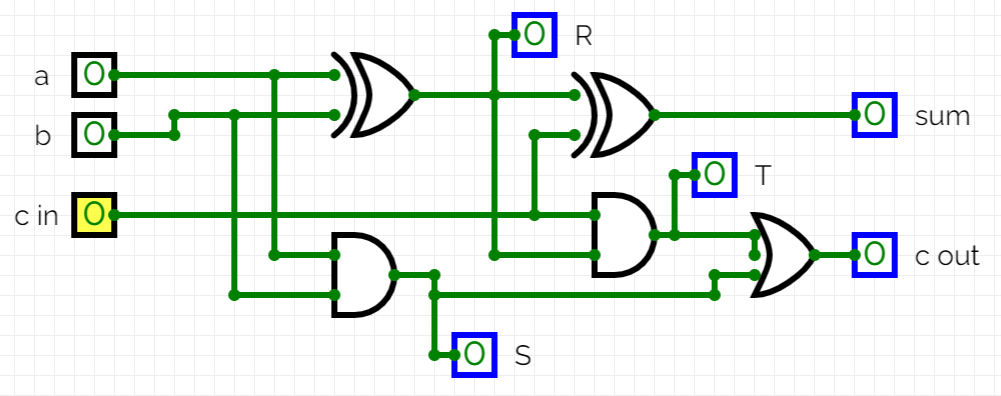
c = 1The output bits will become as per table above:
sum = 0
c = 1
We can confirm this by simulating the circuit as below:

The Idea
The idea is to add two binary numbers together using the Full Adder logic. I have picked something random below and calculated the sum on paper to cross check the code in Python.
a = 10101
b = 00001

The sum = 010110
Approach
Every code starts with an idea on how to approach the problem to end up with a working solution. My idea was to simply construct few function in Python, to accomplish specific tasks.
XOR function
AND function
OR function
FULL ADDER function
CALCULATE function
The Carry Bit
The output of full adder is a (sum) and a carry (c). The carry bit (c) will be fed back into the circuit each time, for each pair of bits from the binary numbers – starting with (c) = 0.
Code
XOR Gate Function
XOR gate (sometimes EOR, or EXOR and pronounced as Exclusive OR) is a digital logic gate that gives a true (1 or HIGH) output when the number of true inputs is odd.
def XOR(a,b):
    if a != b:
        return 1
    else:
        return 0
The truth table for XOR gate:

AND Gate Function
The AND gate is a basic digital logic gate that implements logical conjunction (∧) from mathematical logic – AND gate behaves according to the truth table above. A HIGH output (1) results only if all the inputs to the AND gate are HIGH (1). If not all inputs to the AND gate are HIGH, LOW output results.
def AND(a,b):
    if a == 1 and b == 1:
        return 1
    else:
        return 0
The truth table for AND gate:

OR Gate Function
The OR gate is a digital logic gate that implements logical disjunction (∨) from mathematical logic – it behaves according to the truth table above. A HIGH output (1) results if one or both the inputs to the gate are HIGH (1). If neither input is high, a LOW output (0) results. In another sense, the function of OR effectively finds the maximum between two binary digits, just as the complementary AND function finds the minimum.
def OR(a,b):
    if a == 0 and b == 0:
        return 0
    else:
        return 1
The truth table for OR gate:

Full Adder Function
A full adder adds binary numbers and accounts for values carried in as well as out. A one-bit full-adder adds three one-bit numbers, often written as A, B, and Ci n; A and B are the operands, and Cin is a bit carried in from the previous less-significant stage. The full adder is usually a component in a cascade of adders, which add 8, 16, 32, etc. bit binary numbers. The circuit produces a two-bit output.
To code it in Python, we have to have a look at the circuit itself again.
The function will take (a), (b) and (c) bits as inputs, compute intermediate stage outputs of (R). (S) and only then the (T) output. The last stage will be the computation of (sum) and (c) bits.
def fulladder(a,b,c):
    R = XOR(a,b)
    S= AND(a,b)
    T= AND(c, R)
    SUM = XOR(R,c)
    c = OR(T,S)
    return SUM, c
Calculate Function
The logic behind the final function is pretty simple. Given two 5 bit binary numbers, iterate through the bits from left to right in pairs and feed the pairs as (a) and (b) inputs into the Full Adder function.
The full adder function will output (sum) and carry (c). The (sum) bit will be appended to the string and the carry (c) bit will be used again with the next pair of input bits.
The final operation is to add the last carry (c) bit value to the stored string.
def calculate():
    a = '10101'
    b = '00001'
    c = 0
    answer = ''
    for i in range(len(a)-1, -1, -1):
        #print(f'a and b =',a[i],b[i])
        SUM, c = fulladder(int(a[i]), int(b[i]), c)
        #print(f'SUM and c =', SUM, c)
        answer += str(SUM)
        #print(f'answer =', answer, '\n')
    answer += str(c)

    print(f'We want =', '010110')
    print(f'We have ', answer[::-1])
Simple? Yeah! Except, because of how the (sum) is added to the string from left to right – and we iterate through the binary numbers from right to left – the answer would be wrong way round! So we reverse the answer and get the correct answer.
Full Adder Circuit Code In Python
Here is the full code with an additional function to check the lengths of the binary numbers. If one is less bits than the other, a row of (0) is added to the front to make them equal.
def checkLength(a,b):
    if a =='': a = '10101'
    if b =='': b = '00001'
    max_len = max(len(a), len(b))
    b1 = a.zfill(max_len)
    b2 = b.zfill(max_len)
    return a, b

def XOR(a,b):
    if a != b:
        return 1
    else:
        return 0

def AND(a,b):
    if a == 1 and b == 1:
        return 1
    else:
        return 0

def OR(a,b):
    if a == 0 and b == 0:
        return 0
    else:
        return 1

def fulladder(a,b,c):
    R = XOR(a,b)
    S= AND(a,b)
    T= AND(c, R)
    SUM = XOR(R,c)
    c = OR(T,S)
    return SUM, c

def calculate():
    a = '10101'
    b = '00001'
    c = 0
    answer = ''
    for i in range(len(a)-1, -1, -1):
        #print(f'a and b =',a[i],b[i])
        SUM, c = fulladder(int(a[i]), int(b[i]), c)
        #print(f'SUM and c =', SUM, c)
        answer += str(SUM)
        #print(f'answer =', answer, '\n')
    answer += str(c)

    print(f'We want =', '010110')
    print(f'We have =', answer[::-1])

calculate()
Sample Output
After running the code, we can capture the console output.
We want = 010110
We have = 010110
Integrating Into Raspberry Pi
I have wrote a code to integrate RPi involving dip switches as inputs and LEDs as outputs, but the demonstration video will follow when I get all the parts and some time to build it. In case anyone wants to have a look, here is the initial design.
# import library
# import RPi.GPIO as GPIO

# set mode to BOARD to call pins by numbers, autodetect RPI model
#
# GPIO.setmode(GPIO.BOARD)


pinsDipSwitch = [1,2,3,4,5,6,7,8]
pinsLedOutput = [9,10,11,12,13]

def xorGate(input1, input2):
    output1 = input1 and (not input2)
    output2 = (not input1) and input2
    return int(output1 or output2)

def halfAdder(input1, input2):
    return (xorGate(input1, input2), input1 and input2)

def fullAdder(input1, input2, carry=0):
    sum1, carry1 = halfAdder(input1, input2)
    sum2, carry2 = halfAdder(sum1, carry)
    return (sum2, carry1 or carry2)

def binaryCircuitAdder(input1, input2):
    carry = 0
    result = ''
    for i in range(len(input1)-1 , -1, -1):
        summ, carry = fullAdder(int(input1[i]), int(input2[i]), carry)
        result += str(summ)
    result += str(carry)
    return result[::-1]

def setIO(inputs, outputs):
    for i in pinsDipSwitch:
        pass
        # setup specific pins as inputs
        #
        # GPIO.setup(i, GPIO.IN)
    print(f'Input pins: ', pinsDipSwitch)
    for o in pinsLedOutput:
        pass
        # setup specific pins as output)
        #
        # GPIO.setup(o, GPIO.OUT)
    print(f'Output pins: ',pinsLedOutput)

def getNumbersDipSwitches(pinsDipSwitch):
    # read input pins
    for p in pinsDipSwitch[0:4]:
        # read status of 4 first input pins
        #
        # binaryNumber1 += str((GPIO.input(p)))
        pass
    print('Reading dip switches positions for 1st binary number done.')
    for p in pinsDipSwitch[4:8]:
        # read status of 4 last input pins
        #
        # binaryNumber2 += str((GPIO.input(p)))
        pass
    print('Reading dip switches positions for 2st binary number done.')

    # If not run on real RPi, let's assign some numbers here
    #
    binaryNumber1 = '1001'
    binaryNumber2 = '0001'
    return binaryNumber1, binaryNumber2

def setOutputLED(binaryNumber):
    countUp = 0
    for pin in pinsLedOutput:
        if int(binaryNumber[countUp]) == 1:
            pass
            print(f'Setting output pin ',pin, 'to HIGH (',binaryNumber[countUp],')')
            # #GPIO.output(pin, GPIO.HIGH)
        else:
            pass
            print(f'Setting output pin ',pin, 'to LOW (',binaryNumber[countUp],')')
            # #GPIO.output(pin, GPIO.LOW)
        countUp += 1
    print('Done, exiting...')
    exit()

def mainFunction():
    setIO(pinsDipSwitch, pinsLedOutput)
    binaryNumber1, binaryNumber2 = getNumbersDipSwitches(pinsDipSwitch)
    print(f'1st binary number is set to: ',binaryNumber1)
    print(f'2nd binary number is set to: ',binaryNumber2)
    addedNumbers = binaryCircuitAdder(binaryNumber1, binaryNumber2)
    print(f'Result of the adder circuit: ',addedNumbers)
    setOutputLED(addedNumbers)

if __name__ == "__main__":
    mainFunction()
else:
    print('Please run directly, exiting...'); quit()