SolidWorks: modelling and drawing a brushed steel part
Why 3D modelling matters in engineering
3D CAD modelling is a core part of modern mechanical engineering, from early concept work all the way to manufacturing:
- Visualisation: Building a solid 3D model makes it much easier to inspect geometry, spot interferences early, and share designs clearly compared to 2D sketches alone.
- Fast iteration: Parametric models are quick to modify, letting you refine dimensions and test variations without machining physical prototypes for every tweak.
- Analysis and optimisation: CAD tools let you check mass properties, clearances, and structural behaviour before anything hits the workshop.
- Collaboration: Models and drawings can be shared cleanly across teams, suppliers, and machinists with less ambiguity.
- Manufacturing output: The same model feeds directly into CNC toolpaths, 3D printing slicers, and production drawings.
This post kicks off a small SolidWorks series where I share 3D parts alongside their technical drawings. If you are learning SolidWorks, download the drawing below and try recreating the part from scratch.
Brushed steel part views
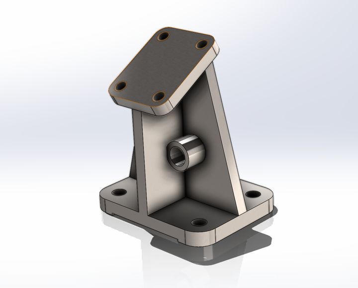
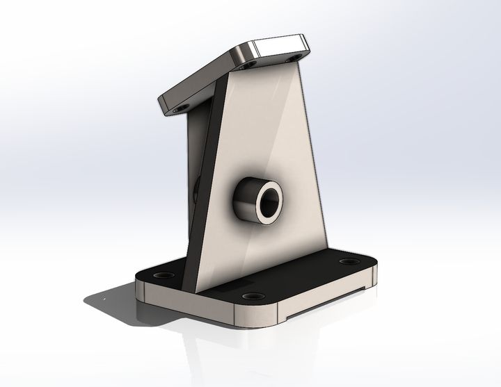
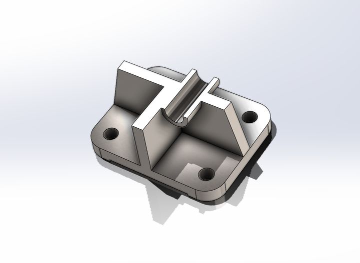
Technical drawing
Download the full SolidWorks technical drawing as a PDF: