
Using SHL For Traffic Lights Sequencer
Here is a simple example of using SHL shift instructions to track the steps during a sequence of traffic lights. The bits pattern stored in a byte will be shifted left and the sequential steps will be activated by the corresponding memory bits. The whole process is programmed in TIA Portal, simulated on the PLCSIM, with a WinCC control panel.
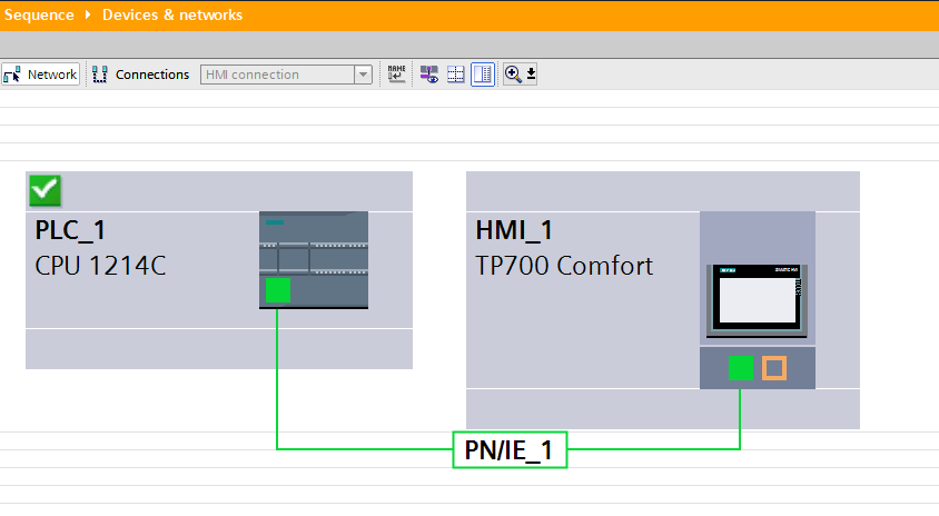
Devices Configuration
Two devices are networked through ethernet connection:
- PLC Siemens 1214C
- HMI Siemens TP700C
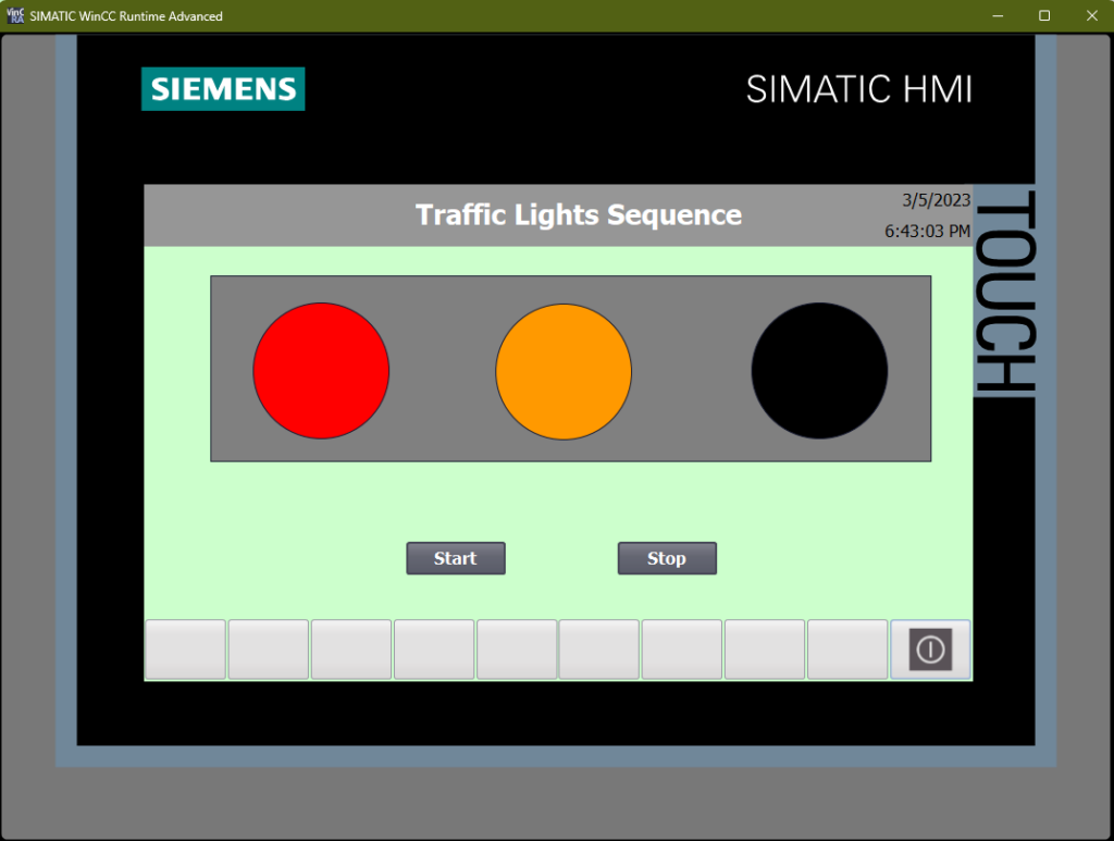
WinCC Design
The HMI screens containts 3 circles representing the traffic lights and a simple Start Stop functionality.
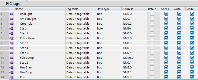
PLC Tags
The tags on the PLC are using Q outputs for the 3 lights and various combination of memory bits to store the logic of steps. MB0 is a byte is used for the shift register that will move the bit left.
Networks
Network 1: Start Stop RS flip-flop
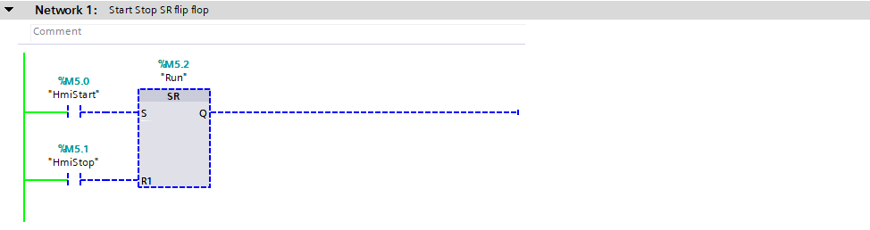
Memory bits M5.0 (Start) and M5.1 (Stop) control the SR that enables the M5.2 (Run) memory bit. It is used to start the whole sequence.
Network 2: Shift register
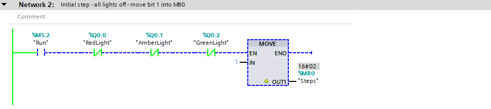
Shift register is loaded with a value of 1 (IN) when the above condition is met.
Network 3: Shifting the bit left
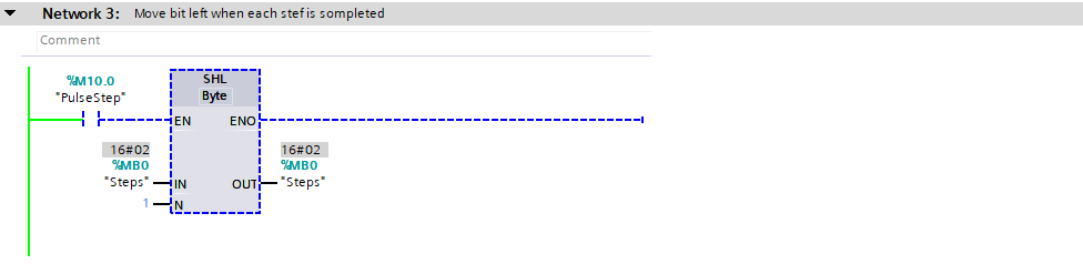
Generate a pulse with memory bit M10.0 (PulseStep). Move 1 to the left, which forces subsequent M0 bits to 1. This enables the next steps in the sequencer below.
Network 4: The sequence of all the steps
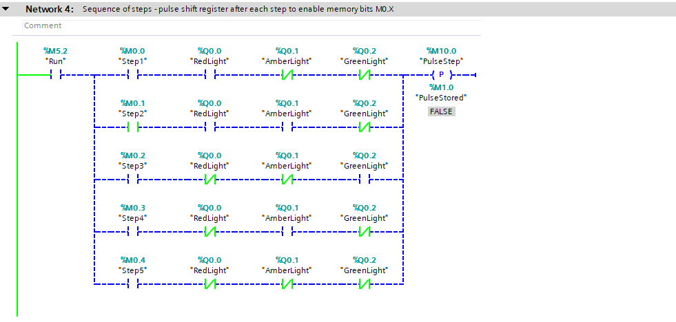
Next steps in the traffic lights sequence are only run, when the corresponding memory bit M0.0 – M0.4 are set to 1. This happens through the shift register (SHL), which moves the bit to the left after each step, because the pulse is generated after previous step is complete.
0000 0001 - initial position, sets M0.0 to 1, Step1 is completed
0000 0010 - sets M0.1, Step2 is completed and so on
Network 5: Step 1 Red Light
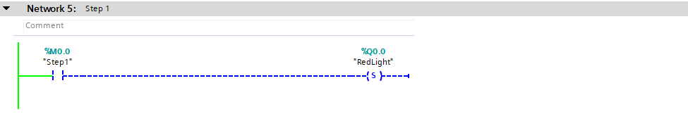
Red light output is Set to 1.
Network 6: Step 2 Amber Light
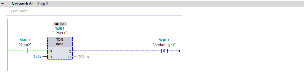
Amber light output is Set to 1 after 5 seconds.
Network 7: Step 3 Green Light
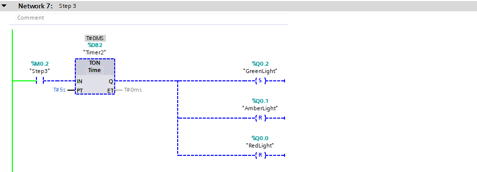
After 5 seconds, the Green light is Set to 1. At this point, Amber and Red lights are Reset to 0 at the same time.
Network 8: Step 4 Amber Light
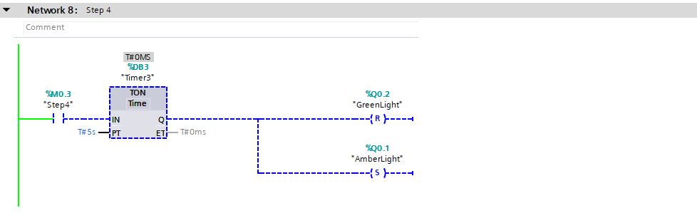
After 5 seconds, the Green light output is Reset and Amber light is Set back on.
Network 9: Step 5
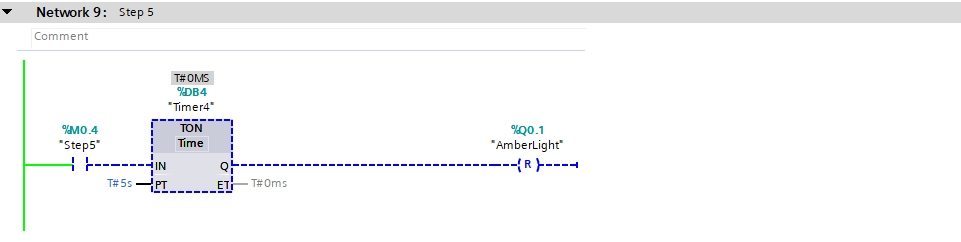
Last step is to Reset the Amber light output back to 0. This completes the sequence, which makes Network 2 to be True again (all lights off – send the value 1 into shift register).
Network 10: Stop and Reset
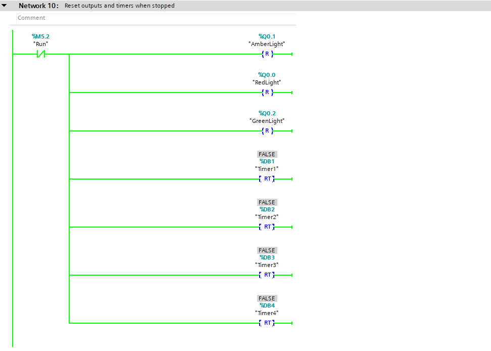
This network activates when HMI Stop is pressed, which Resets the M5.2 (Run) signal. It Resets all lights outputs to 0 and also instantly resets the timers (RT).