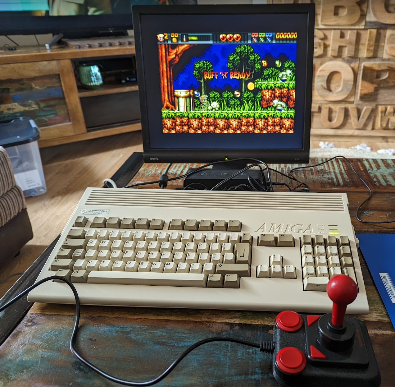
Modifying your Competition Pro joystick to work with an Amiga computer can be a fun and rewarding project for retro gaming enthusiasts. One common modification involves replacing the joystick’s USB plug with a DB9 plug, which is the standard connector used by the Amiga. A bit of solder, extra wires and a correct pin-out is all is needed to enjoy classic Amiga games.
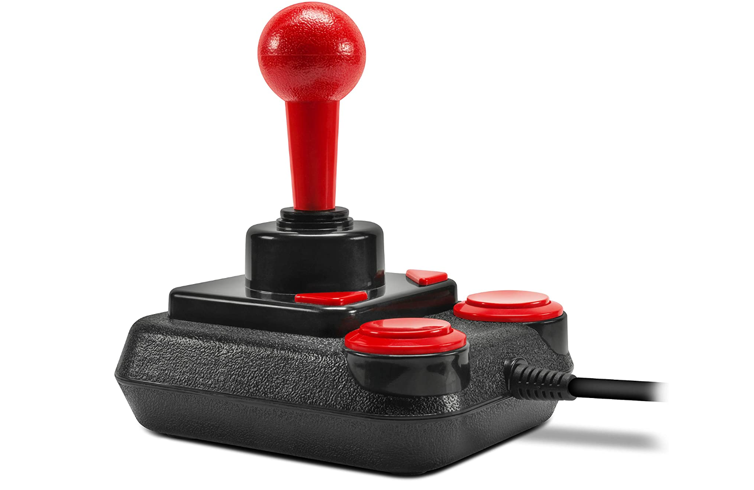
Speedlink Competition Pro Extra USB Joystick
The model that I have modified is described as SL-650212-BKRD. You can get it for around £29 on various websites. Any model similar to this one will work, as long as it has microswitches (normally open contacts).
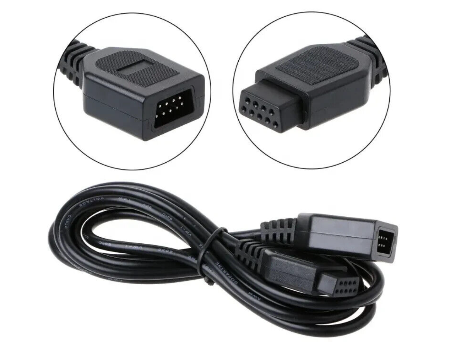
9 Pin Extension Cable
For the conversion, the Amiga / Atari extension cable is needed. You can grab one of these on Ebay. It is a 9 pin cable male / female.
The female part (port) is glued together. Use a sharp knife to cut around the sides to open it up. Desolder the connections to the pins inside the plug and extend them with any wires. I used a variety of colour to extend them, so they reach the switches inside the joystick enlclosure.
The cable itself, can we found at the link below. If it is sold out, look for 9 pin DB9 Amiga or Atari cable.
https://www.ebay.co.uk/itm/165579811407
Amiga DB9 Pin Out
Let’s start with figuring out the pin out. Cut off the female part of the cable and strip off the insulation from all the available wires. Using the multimeter, check the continuity to determine which pin corresponds with which wire. Use the below schematic for the pins.
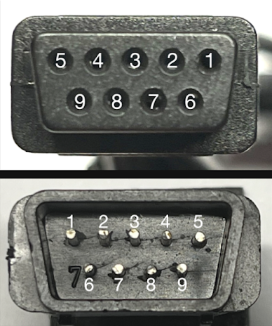
After determining the colours of wires, they should be matches with corresponding pins, as per the below. If, for example, your extension cable has a red wire and checking its continuity shows a connection to pin 1 – it must be used for UP switch. The best way around it is to write it all down.
pin 1 - UP
pin 2 - DOWN
pin 3 - LEFT
pin 4 - RIGHT
pin 5 - n/a
pin 6 - FIRE
pin 7 - n/a
pin 8 - GROUND
pin 9 - n/a
The Joystick
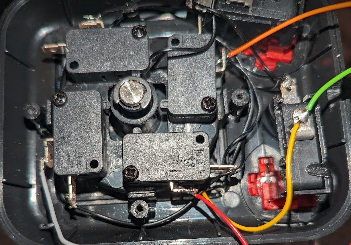
The Competition Pro needs a very little modification. The USB module needs to be removed and the cable entry hole into the joystick’s body needs to be enlarged a little bit, as the extension cord is thicker than the original USB one.
Removed USB module should leave the inside just with the switches. It is quite clear these are NO / NC contacts. The cable entry can be seen on the right.
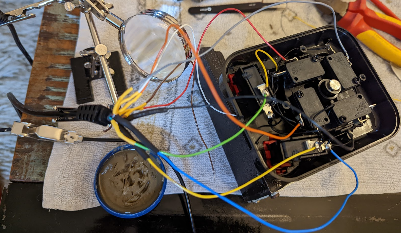
USB To DB9 Conversion
The finished modification should look something like the below.
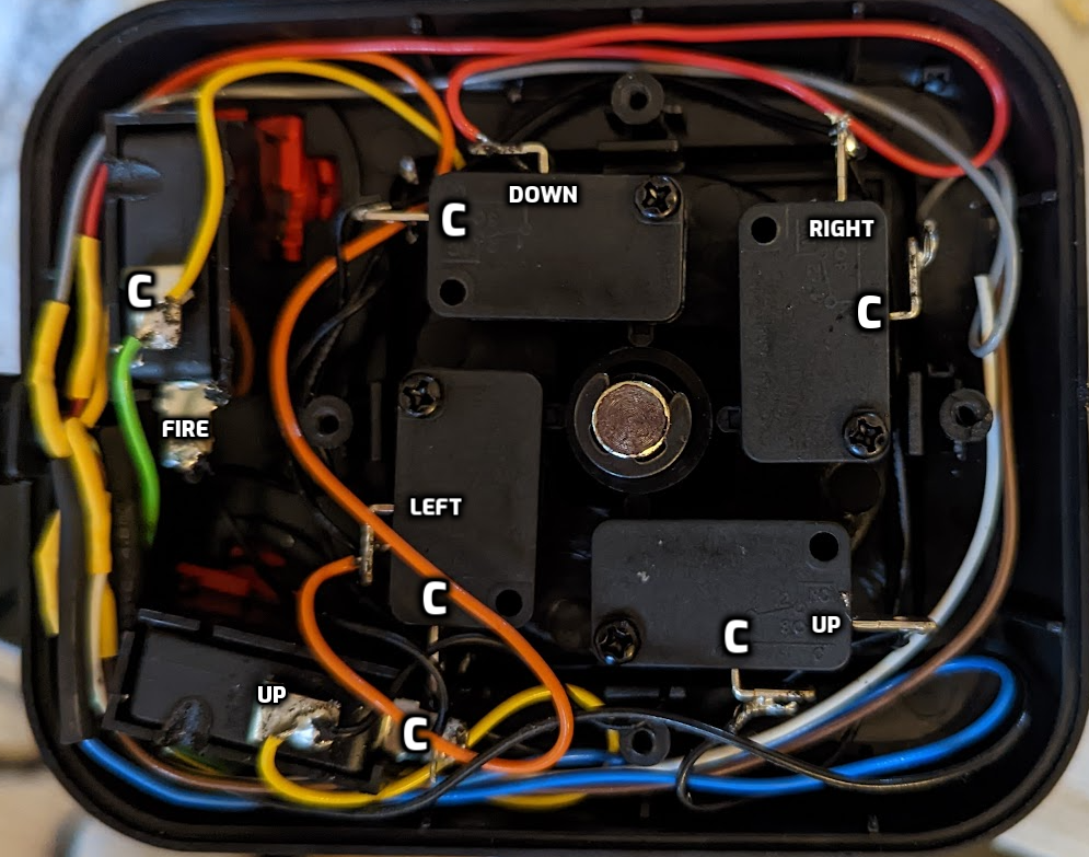
The (C) common connection is a single wire interconnected between all the (C) points and is wired to pin 8 of the extension cable, whichever colour it is.
Things To Consider
Orientation Of The Joystick
I decided to use the joystick with the buttons on the left hand side, so my (UP) direction is as shown on the above photograph.
Second Button As A Jump Button
The top button of the joystick is wired in parallel with the (UP) connection point, so I can use it as an optional UP signal when pressed.
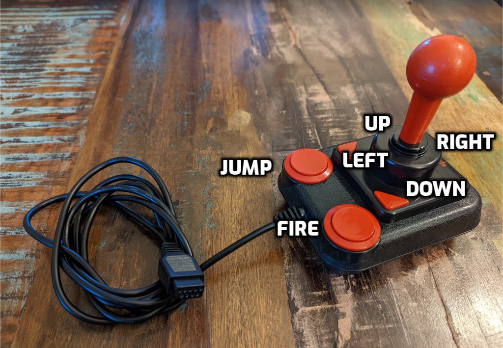
Finished Conversion
The modification is simple. Connect pin 8 to all (C) points and the rest to your preffered switches. Wire (UP) with parallel to the second button for an additional jump button. Don’t forget to test it!